Hardware implemented image processor and object detector
a team effort to develop a self-driving rover
Our team developed a rover with the objective being able to navigate an arena autonomously, detecting objects and communicating with a web-application via wireless connection to report this information. The information was then used to update the live map of the arena on the web-application for the user to view. The rover had an onboard FPGA, microprocessor, and energy system.
The rover comprised of various sub-systems:
-
Command: A software system running on a microprocessor onboard the rover which was responsible for establishing a wireless connection to the server, communicating with the FPGA to receive information about the rovers surroundings and for running the path-finding algorithm.
-
Vision: A hardware based image processor that processed frames inputted by the camera module onboard the FPGA.
-
Energy and Drive: This subsystem comprised of the battery system and control system that managed the motors to manage driving the rover.
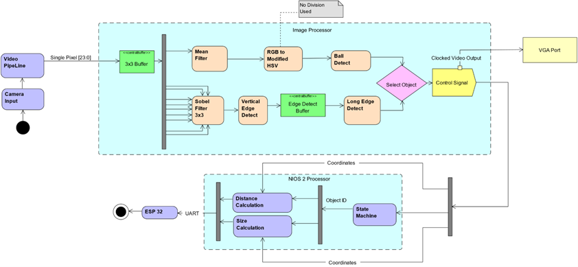
I was responsible for developing the vision sub-system. The camera module would input the video feed frame by frame, pixel by pixel to the FPGA. The pixels were then processed, and through a software interface, control signals could be sent across the UART connection to the micro-processor. Using a hardware implemented image processor, one could attain much better throughput of video-frames when compared to implementing an image processor on a software layer using python.
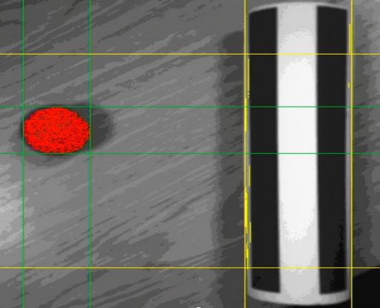
The pixels were inputted as 24-bit RGB values. To be able to detect objects based on colour, the pixels were mapped from the RGB colour-space to the HSV colour-space. As a result, one could check against a pixels HSV values, for example, to detect the red ball, I would compare the hue value against a lower and upper bound. If the hue, value and saturation were all within the accepted range, that pixel would be identified as “red”. Then, I used convolution layers to expand the receptive field, we could identify if an object was red or not and bound the object. Additionally, by applying Sobel filters to the pixels, we could detect lines and hence the striped building.
Latency and throughput were both priorities for the following reasons: if latency was low, the rover would act using information that isn’t accurate since time would have elapsed since pixels were processed. If the throughput was low, the number of frames processed per second would be low, meaning that the rover would have time gaps where it was not receiving new information.
As a result, I employed various techniques to try to improve the performance. For example, the filtering was done using FIFOs implemented using registers, although this was very costly on resource utilisation. Additionally, I created pipelines where possible to be able to retain high throughput.
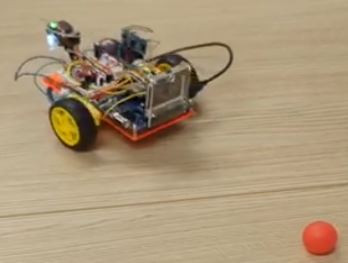
Since the command sub-system was limited by the micro-processor used, our path-finding algorithm had to be very light on compute. Something like the A-star algorithm was not performant enough to be viable. As a result, we decided to use a very primitive algorithm whereby the rover would scan the area around it by rotating 360 degrees. If it could not find a ball, it would move in a direction where there were no walls and scan again. Once it found a ball, it would move towards it until the distance could be reliably measured and then once the ball was mapped, it would begin scanning again. The video below demonstrates this - see how the rover rotates at the end since it is searching for more balls to map.